
By Andrew Timmerman, global engineering manager, Martin Engineering
Wandering conveyor belts might begin as small irritations but left unchecked these can have serious consequences, not just in terms of productivity but also maintenance costs and safety risks. Even a slight belt misalignment and drifting can lead to a variety of issues which, especially over time, can lead to full-blown conveyor catastrophes and days of unplanned downtime (Figure 1).
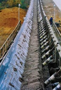
Figure 1: Belt mistracking can lead to catastrophic failure if left unchecked. All images supplied ©Martin Engineering 2025
Firstly, it’s common for a misaligned belt to come into contact with the conveyor framework, causing fraying, shredding or splice damage. If this condition isn’t noticed
and addressed right away, great lengths of valuable belting can be destroyed.
Furthermore, a belt can cause severe damage to a conveyor system’s structure. In fact, a high-speed belt edge rubbing on the support structure can cut through steel mounts with surprising speed, threatening structural integrity (Figure 2).
A compromised bracket or support can cause a major failure, which could in turn damage other components of the system. All these consequences of mistracking result in added expenses, increased maintenance, reduced efficiency and greater risk.
Besides the many causes of mistracking, the belt training system that’s installed with the conveyor may in some cases actually worsen the problem. Increased belt speeds and greater cargo loads mean that some systems are equipped with belt tracking devices that aren’t able to handle the higher thresholds.
In most cases, however, mistracking is a problem that can be corrected. Belt behavior is based on a set of principles which serve as the guidelines for ‘belt training’, the process of adjusting the conveyor structure, rolling components and load conditions to correctly centre the belt. Wandering is prevented by first understanding the basic patterns of belt behaviour and then following established procedures to carefully align the structure and components to correct any fluctuations in the belt’s path.
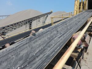
Figure 2: Conveyor belts that are out of alignment are capable of ‘sawing’ through steel components, in this case a seized training idler.
Mistracking indicators
Belt drift can begin in any part of the conveyor system, and identifying mistracking through a comprehensive review of the entire conveyor system (such as Martin Engineering’s Walk The Belt™ program) is the first step toward correction. All these traits could be indicators of belt mistracking, which itself could have one or more root causes (Figure 2).
- Edge Fraying (Figure 3) – probably an indication that the belt is rubbing on the conveyor frame at some point, degrading the edge, reducing the usable width and increasing the chance of a fire.
- Excessive spillage – could mean that one side of the belt has drifted higher on the trough angle, allowing cargo to discharge along the belt path.
- Idler fouling – an off-centre load and uneven belt plane can foul idlers. Bearing abrasion can then cause the idler to seize, and the ensuing friction against the running belt can erode its coating and increase the risk of fire.
- Off-centre at head or tail pulley – this type of drift can lead to a fast-moving belt coming in contact with the conveyor stringer structure. There is also a chance of splice failure, which puts the entire system in jeopardy and creates heightened safety risks.
- Lack of tail pulley protection – on many systems, the belt collects lumps of spilled material on the non-carrying side. If these objects are not removed, they can become trapped between the tail pulley and the belt, causing mistracking and often doing significant damage to both.
- Uneven discharge – as the belt drifts to either side of the head pulley, the belt cleaners do not properly clean the entire surface, causing excessive carryback. Material collects on the pulleys and structure, fouling the return side of the belt, resulting in slippage, lost product and other negative effects.
- Uneven loading – if the belt path leading from the tail pulley into the loading zone is uneven, the cargo can be loaded off- centre and cause excessive spillage. This may also be caused by inadequate transfer point design.
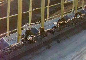
Figure 3: Contact with the support structure can cause serious belt damage.
Identification begins at the head pulley
Starting at the head pulley, the belt should also be inspected for cupping, bow/camber (a long curvature) or crooked splicing. When observing the empty belt running over the head pulley, a cambered belt will drift to one side in the middle of the camber and then slowly return to centre as the belt travels through the head pulley.
If a splice is crooked, the belt’s path will jump quickly to one side as the splice travels over the pulley.
If it is discovered that these factors are the cause of mistracking, simply adjusting the conveyor’s rolling components will not correct the issue. The only options are either replacing the entire belt, or – in the case of crooked splice(s) – re-splicing the belt, assuming there is enough extra belting in the take-up system to allow removal of the faulty splice section.
During the observation procedure, if the belt moves to one side and stays there, the problem may be one of three things: the head pulley lagging is not consistent, the last few carrying idlers prior to the pulley are out of alignment or the head pulley itself is not properly adjusted.
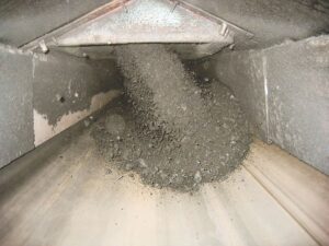
Figure 4: Off-centre loading can be a root cause of belt mistracking with the cargo weight typically pushing the belt toward the more lightly loaded side.
Mistracking after the head pulley
Mistracking just after the head pulley on the conveyor’s return has two main causes. The first might be that the lagging is missing on one end of the pulley, so the pulley’s diameter is off-centre, placing uneven pressure on the belt and causing it to wander. If this is not the case, then the belt cleaning system may have been mounted slightly askew, putting greater pressure on one side of the belt and pulley. This uneven friction can also lead to mistracking.
Once the type of misalignment has been identified, the cause can be sought. There are three groups of common causes for mistracking. The first is a fault with the belt or splice, second is the conveyor’s structure, components or environment, and third is due to improper material loading.”
Belt and splice
If the belt is poorly manufactured or stored improperly, it can bow or camber. Poor installation of a vulcanised or mechanical splice can result in a splice that causes belt tracking problems. Exposure to the elements or to chemicals can degrade the carcass (plies or cords) and the cover of the belt. Faults and damage caused by mismatching the belt to the application and/or operating environment can require frequent replacement.
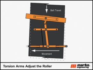
Figure 5: The Torsion Arms sense changes in the belt path and adjust the roller to compensate.
Conveyor structure
Inaccurate alignment of the conveyor stringer structure can have subtle but lasting effects on the belt’s performance. Structural misalignment can happen due to age, machinery collisions, seismic activity effects or ground settling.
Environmental factors
High winds require “wind loops” to keep the belt in line. Exposure to extreme temperatures on one side of the conveyor can make components expand, causing changes in friction.
Improper loading
The load’s centre of gravity will seek the lowest point of the troughing idlers, so if the belt is not centre loaded, the weight of the cargo pushes the belt toward the conveyor’s more lightly-loaded side (Figure 4).
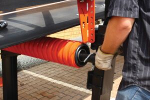
Figure 6: This roller tracker uses a unique ribbed lagging made of durable
polyurethane to increase performance.
Belt training
A common procedure to correct the wandering belt is to slightly adjust the return and carrying idlers against the direction of the mistracking. Unfortunately, this approach does not work on reversing belts. An even more serious consequence is that over time a number of the idlers may be misaligned, effectively “fighting” each other to correct the alignment.
When idler training is not successful as a long-term solution, operators may be faced with a situation where the training procedure is repeated on a frequent (sometimes daily) basis. At that point, managers should consider installing some form of engineered training solution to mitigate the problem (Figure 5).
Engineered training solutions are devices that sense the position of a belt and, through a mechanism or geometry change, actively adjust its path. Some of the most common types include:
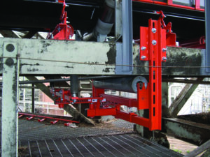
Figure 7: The in-line sensing roll trainer has a carrying roll on a central pivot bearing with vertical guide rolls mounted on both sides.
- Belt misalignment switches – the wandering belt pushes a lever arm and activates a switch, which either sets off an alarm or stops the system. Costly downtime can result from these systems. Vertical edge guides –these are positioned perpendicular to the belt’s path to keep the edge away from the conveyor structure and should not be used to compensate for persistent misalignment problems. These are most practical on short, low-tension systems and not particularly effective on thin belts – operators have experienced the belt roll over on itself.
- Vee idlers and rollers – set on both the cargo side and return side of the belt, these use a trough configuration and edge brackets that rely on a centreing force to correct the belt path, which can add stress on the belt and lead to damage. These systems are more expensive and require more maintenance than a conventional return idler.
- Crowned pulleys – the raised portion of the pulley (the crown) touches the belt first and the outer sections of the belt on both sides produce a force driving it toward the centre (Figure 6).
- Dynamic belt-tracking systems – these use the force of the mistracking belt on an arm that moves an idler, creating a steering action that directs the belt back into the centre. In-line sensing roll trainers have vertical guide rolls that are mounted on both sides of the belt, in line with the roller, with the centreline running through the idler’s pivot point. Movement of the belt against either guide roll causes the roll to move in the direction of the misalignment, pivoting the entire idler (Figure 7).
- Leading sensing-roll trainers – employing either a pivoting carrying roll or troughing set, short arms on both sides of the frame are positioned in advance of the pivoting roller and end in guide rolls located 25 to 75mm (1 to 3 inches) from the belt edge. Torsion-spring trainers – these improve upon the leading sensing-roll trainer design by removing one sensing roll and incorporating a spring into the pivot, which keeps the one remaining sensing roll in constant contact with the belt edge.
- Multi-pivot belt trainers use longer arms than other designs, positioning the guide rolls further from the pivot roller, as well as closer to the belt edge. The closer proximity allows guide rolls to sense slight misalignments and make immediate corrections. Rather than waiting for a powerful mistracking force, the longer arms require considerably less force to move the pivot roller. The result is better correction with no pinch points and less wear on conveyor and tracking equipment, for a longer and more efficient service life (Figure 8).
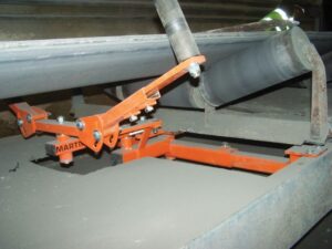
Figure 8: Multi-pivot belt trainers use a torque-multiplying system to improve belt path correction.
Total conveyor analysis
Installing trackers is an economical solution, but operators should do a full analysis and consider addressing other causal issues. By focusing solely on belt alignment, plant personnel may miss other opportunities to increase performance and relieve some of the burden on their system.
Off-centred loading remains a major cause of mistracking. This can be corrected by installing a central loading transfer chute or by using deflectors, grids or chute bottoms that can be adjusted to correct the placement of the load on the belt. Some conveyor accessory manufacturers offer well-engineered modern equipment such as load-centring transfer chutes, high-impact cradles, adjustable slider cradles, an assortment of cleaner blades created for specific applications and redesigned chute box technology.
Keeping the belt centred and moving quickly is the key to high production, a low cost of operation and a safer workplace. Misalignment causes downtime and costsmoney. But nothing causes more downtime and expense than a structural collapse, a destructive belt fire or other catastrophies as a result of inattention to early signs of mistracking.
 |
Introducing Andrew Timmerman: Global engineering manager, Martin Engineering, Timmerman earned a Mechanical Engineering degree with a minor in Applied Mathematics from Northern Illinois University. He joined Martin Engineering in 2011 as a product development engineer and currently holds the position of engineering supervisor. Timmerman’s primary responsibilities are in R&D and Engineering, where the bulk of his time is dedicated to the mechanical design of products and processes, as well as integration of electronic components into the company’s mechanical systems to continue development of “smart” products for bulk material handling applications. |